System approach in pumping systems.
Every pumping system consists of various components.
Every component influences others.
The Efficiency of a complete pump system depends on the coordinated operation of all components.
You can select hight efficient components (pump, electric motor, VFD etc) but the efficiency of a complete system will be low.
The GOAL is to minimize the operating cost of the pumping system
The system approach allows taking into account the operation of all components and their influence on each other.
What main errors users do when they decide to improve the efficiency of a pumping system?
Consideration only elements usually pump or electric motor. The common decision is the replacement of the installed pump by a pump with higher efficiency and replacement of a standard electric motor by a motor with a higher efficiency index.
But even after a replacement, the efficiency of a complete system can leave at the same level.
To understand How to reduce the energy consumption in a pumping system, let's define what factors influence it?
Defining the system boundaries
Output = Flow rate * Head *constant
Which flow rate?
Which head?

When looking at a system it is very important to set the boundaries of the system right.
The figure shows a simple system where the pump handles liquid from one reservoir to another situated at a higher elevation.
If the inner box Blue color is chosen as the system boundary, we might determine that the system is very efficient as we check power, flow rate, and head.
If the middlebox is chosen (orange), the picture probably gets worse. We now see that there is a control valve which throttles flow and that part of the flow is returned to the first tank through a by-pass line.
All flow measured by the flow meter F1 is therefore not being used, and the energy is used for pumping the liquid back into the tank is wasted.
If the largest box is used as the system boundary, we get the true picture of what the system demand is. By measuring the flow at F2 we will know how much of the pumped liquid that is really being delivered to the second tank. The pressure across the throttling valve is also wasted.
The true system demands will be determined by looking at the pressure and flow rate that is necessary to achieve the same flow rate with the bypass line closed and the throttling valve removed.
Example


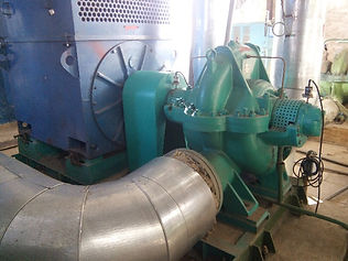
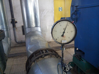
Discharge Pressure gauge – 14 bars

Inlet Pressure gauge – 3.2 bars
Differential pressure 14-3.2= 10.8 bars
Pump head ~ 110 m
The operating point is very close to the Best efficiency point.
BUT
If look at the system wider
Control valve #1 Closed on 40%


Another Control valve closed on a half

CONCLUSIONS
DO NOT CONCENTRATE AT THE PUMP OR ELECTRIC MOTOR.
Concentrating on elements You will not get all savings.
LOOK AT THE COMPLETE SYSTEM AND END USERS.
Define the real requirement of the end-user.
SYSTEM APPROACH IS THE MOST EFFECTIVE METHOD WHICH GIVES THE MAXIMUM EFFECTIVE.
THINK ABOUT WHAT POTENTIAL IMPROVEMENTS FOR THE SYSTEM CAN BE DONE?